
Inputs & outputs
Configure I/O signals, convert raw readings into useful units and manage the module layout.
Open Devices → RevPi I/O to configure the signals connected to the RevPi’s expansion modules. You can name signals and scale raw readings into the units you need, such as volts, degrees Celsius or centimetres.
Module and port map
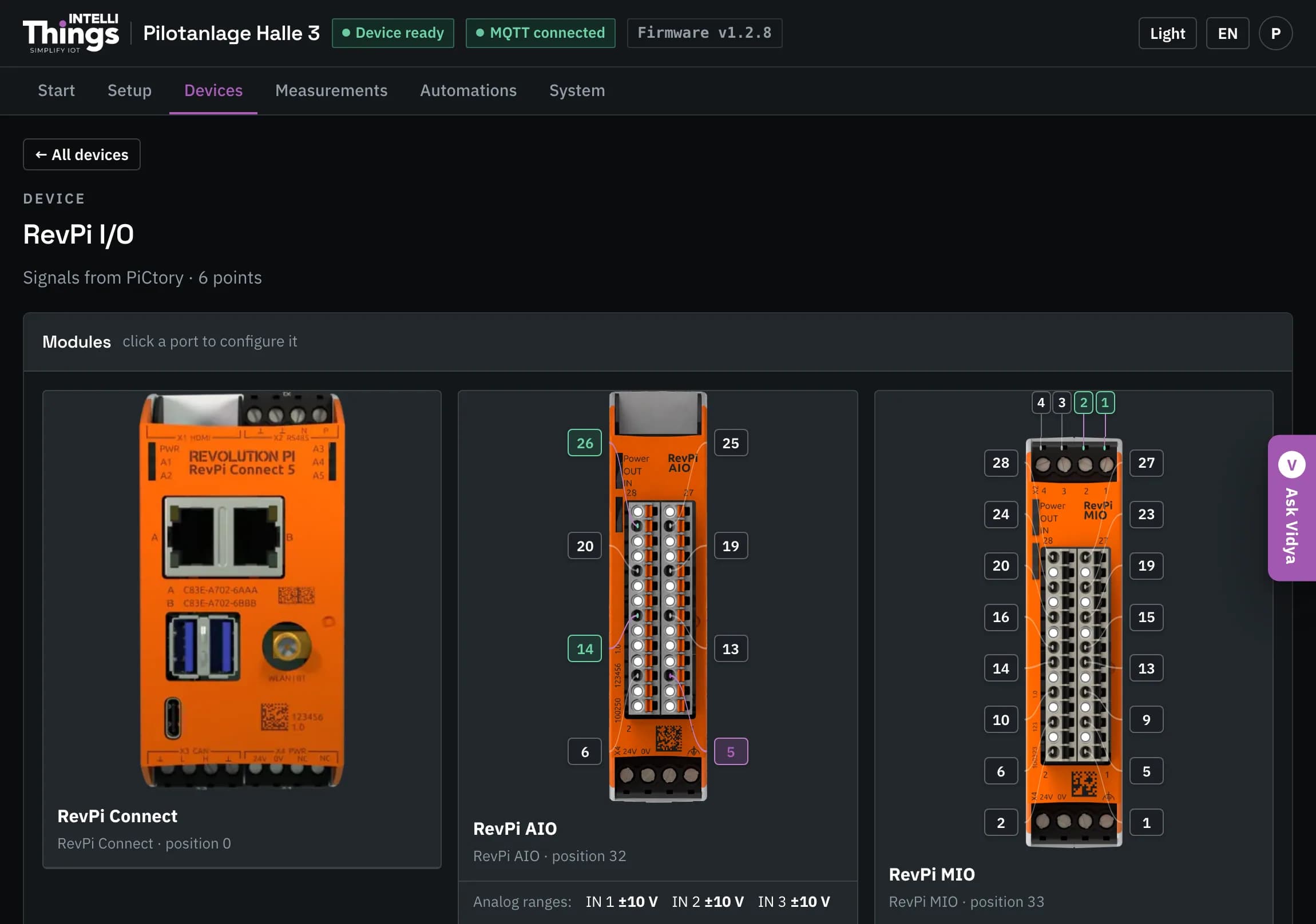
Each fitted module is shown as a photo. The numbered markers match the port numbers printed on the module, so you can identify the corresponding connections in your cabinet. Each marker’s appearance shows the port’s configuration and reading status:
| Marker | Meaning |
|---|---|
| Plain | The port has not been configured. |
| Violet border | The port is configured, but no reading has arrived. |
| Green border | The port is configured and providing readings. |
| Dashed and smaller | A connection with no signal of its own, such as GND. Click it to view its purpose. |
Under an AIO module, Analog ranges shows the configured range for each channel, such as OUT 1 4–20 mA. A red entry, such as OUT 2 off, indicates that the channel is switched off. These are module settings. To change them, use Change the module layout, described under Changing which modules are fitted.
Not shown on the photo yet lists signals without a marker in the photo, such as counters. Selecting one opens the same settings panel.
Which port is which
Analog signals represent values that vary over a range, such as pressure or temperature. Digital signals have two states: on and off.
AIO module
| Port | Signal |
|---|---|
| 26, 25, 19, 13 | Analog input 1 – 4 |
| 14, 20 | Temperature sensor (PT100/PT1000) 1 – 2 |
| 5, 6 | Analog output 1 – 2 |
MIO module
| Port | Signal |
|---|---|
| X2 pins 1 – 4 | Digital input or output, PWM, counter (all on the same pin) |
| 1, 2, 5, 6, 9, 10, 13, 14 | Analog input 1 – 8 |
| 15, 16, 19, 20, 23, 24, 27, 28 | Analog output 1 – 8 |
Multiple signals on one port
A port can have more than one associated signal, such as a measurement and its status. Click the port to open one panel with a tab for each signal or function. This keeps the settings for the same physical connection together.
Setting up a port
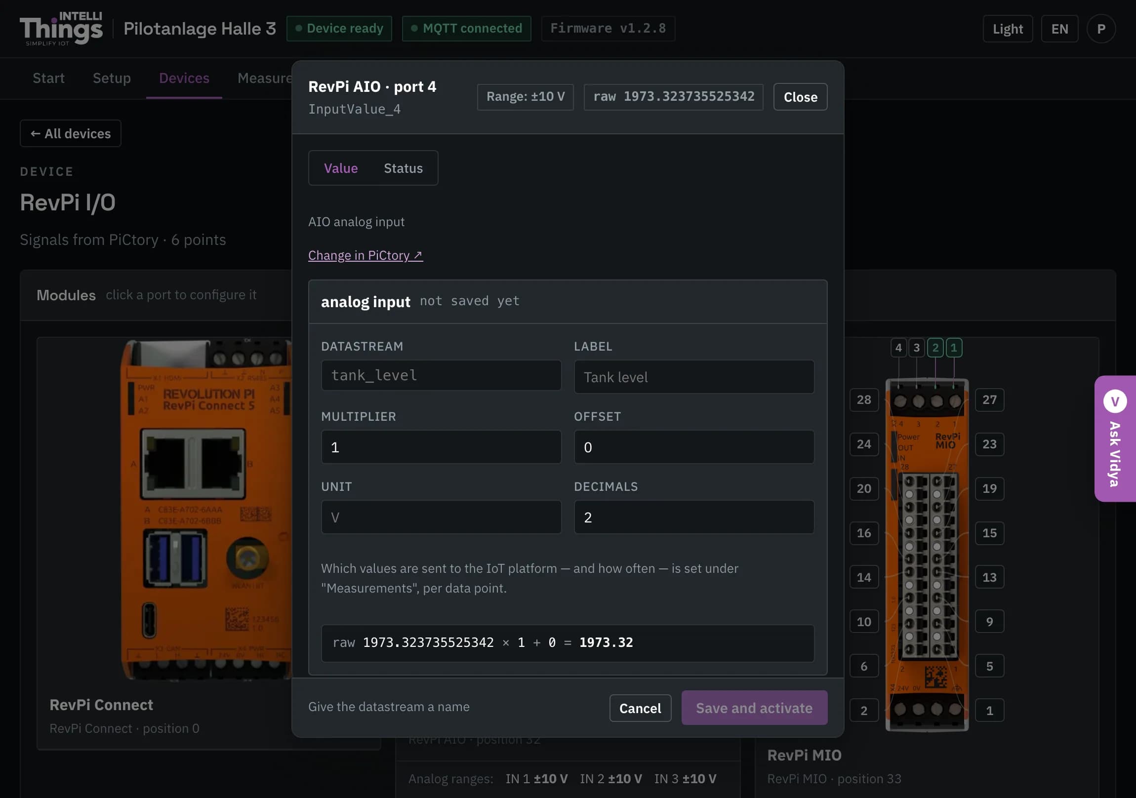
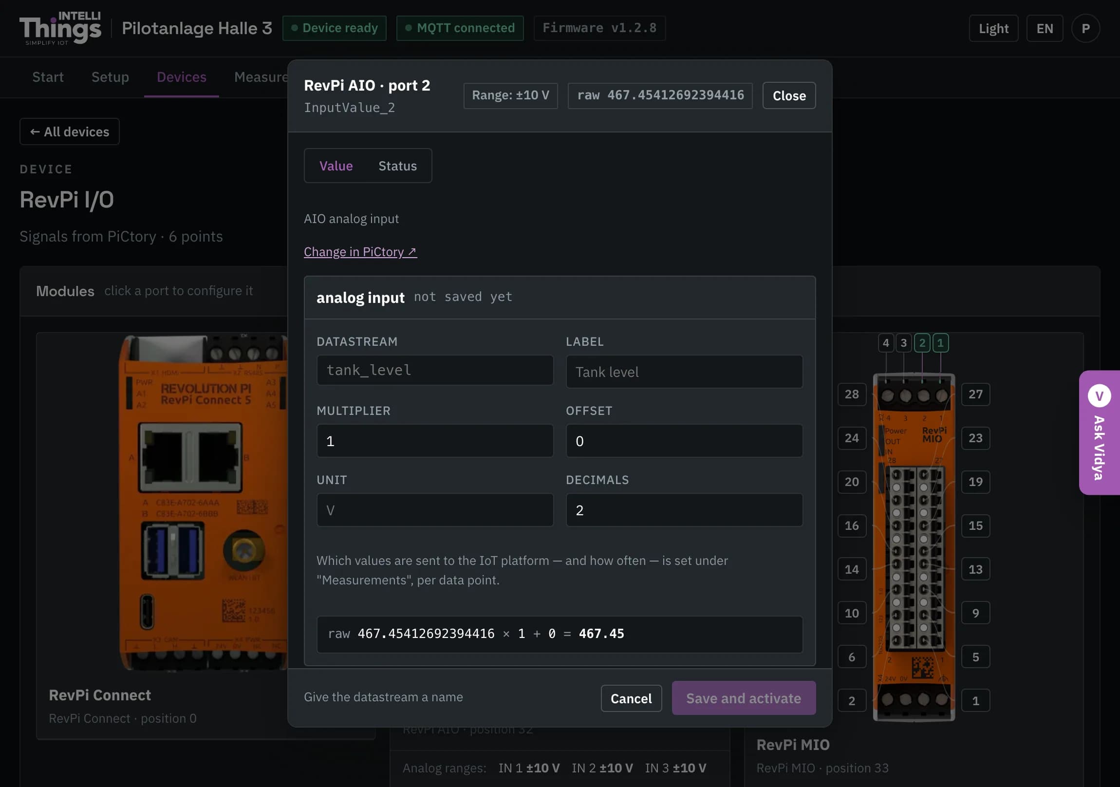
Click the port in the photo. The settings panel opens with default values already filled in. Its heading identifies the port type and save status, for example analog input · not saved yet. The module determines the port type, so you do not need to select it in this panel.
Enter a name for the reading. This is the only required entry. Adjust the other settings as needed.
Click Save and activate. This saves the settings and closes the panel. Until you save, the settings remain unchanged on the RevPi. Cancel discards your edits.
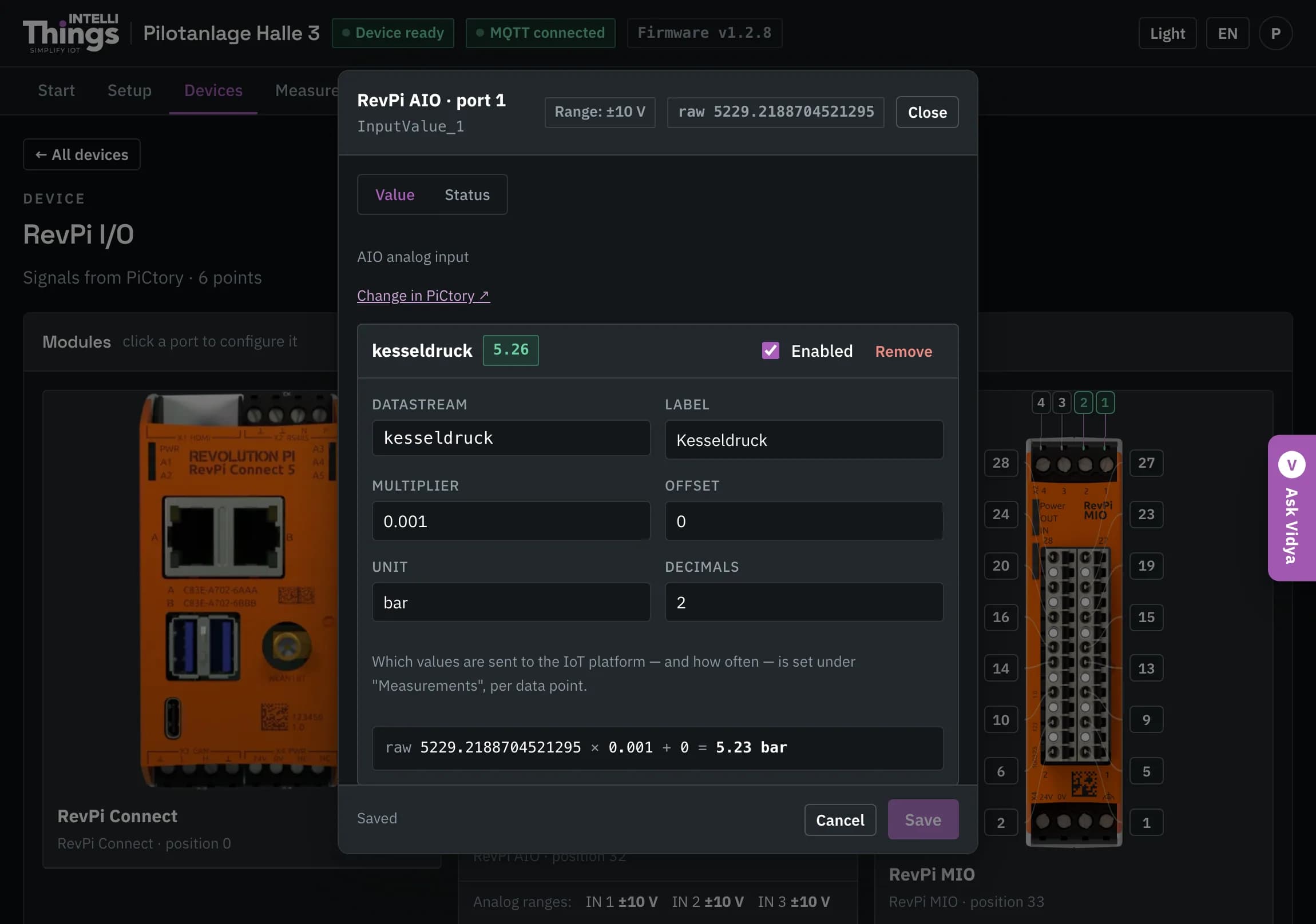
To edit an existing port configuration, open the port in the same way. Save becomes available when you change a setting. Remove deletes the configuration entry.
The top of the panel shows the module, port, technical name and live reading directly from the hardware. Use this reading to check whether a connected sensor is providing a signal.
Port settings
| Field | What it means |
|---|---|
| Datastream | The name intelliThings CORE uses for this reading, for example kesseldruck. It must be unique on this RevPi and contain only lowercase letters, digits and underscores. |
| Label | The display name shown throughout the dashboard, for example “Boiler pressure”. |
| Enabled | Determines whether the signal is read. |
| Multiplier / Offset / Unit / Decimals | Settings for converting and displaying the raw reading. See below. |
| Polarity (digital inputs only) | Active high reports “on” when voltage is present at the pin. Active low is used for contacts that are closed at rest. |
| Command key (outputs only) | The key used in platform commands to control this output. For example, pumpe is the key in {"pumpe": 1}. |
To choose which readings to send to intelliThings CORE, open Measurements. This page controls sending for all devices. See Sending to the platform.
Convert raw readings into the units you need
The hardware reports a raw value, for example in millivolts. Scaling converts this value into the quantity and unit you want to display. Multiplier sets the conversion factor, and Offset is added after multiplication. Unit specifies the displayed unit; Decimals sets the number of decimal places:
displayed value = raw value × Multiplier + Offset, rounded to DecimalsThe preview below the form applies these settings to the current reading, so you can check the result before saving.
| Where the value comes from | What the hardware reports | Example |
|---|---|---|
| MIO analog input | millivolts | × 0.001 gives volts, unit V |
| AIO temperature sensor | tenths of a degree | × 0.1 gives °C |
| AIO analog input | millivolts or microamps, depending on the range | A 0–10 V sensor measuring 0–250 cm: × 0.025, unit cm |
In the last example, 10 V corresponds to a raw reading of 10,000 mV. Multiplying by 0.025 gives 250 cm, the upper end of the sensor’s measurement range.
Outputs
For outputs, the RevPi reverses the scaling calculation: it converts the value sent by the platform, expressed in the configured unit, into the value required by the hardware.
The output settings panel also contains a Test box. Enter a value and click Set to apply it to the output immediately.
Output commands act on connected equipment immediately
A test value, platform command or automation rule acts immediately on the equipment connected to the output. Make sure it is safe to operate the connected equipment before testing an output.
Changing which modules are fitted
At the bottom of the page, Change the module layout (like PiCtory) opens the editor for the fitted modules and their channel functions. PiCtory is the RevPi’s module configuration tool. This editor writes the same settings from within the dashboard.
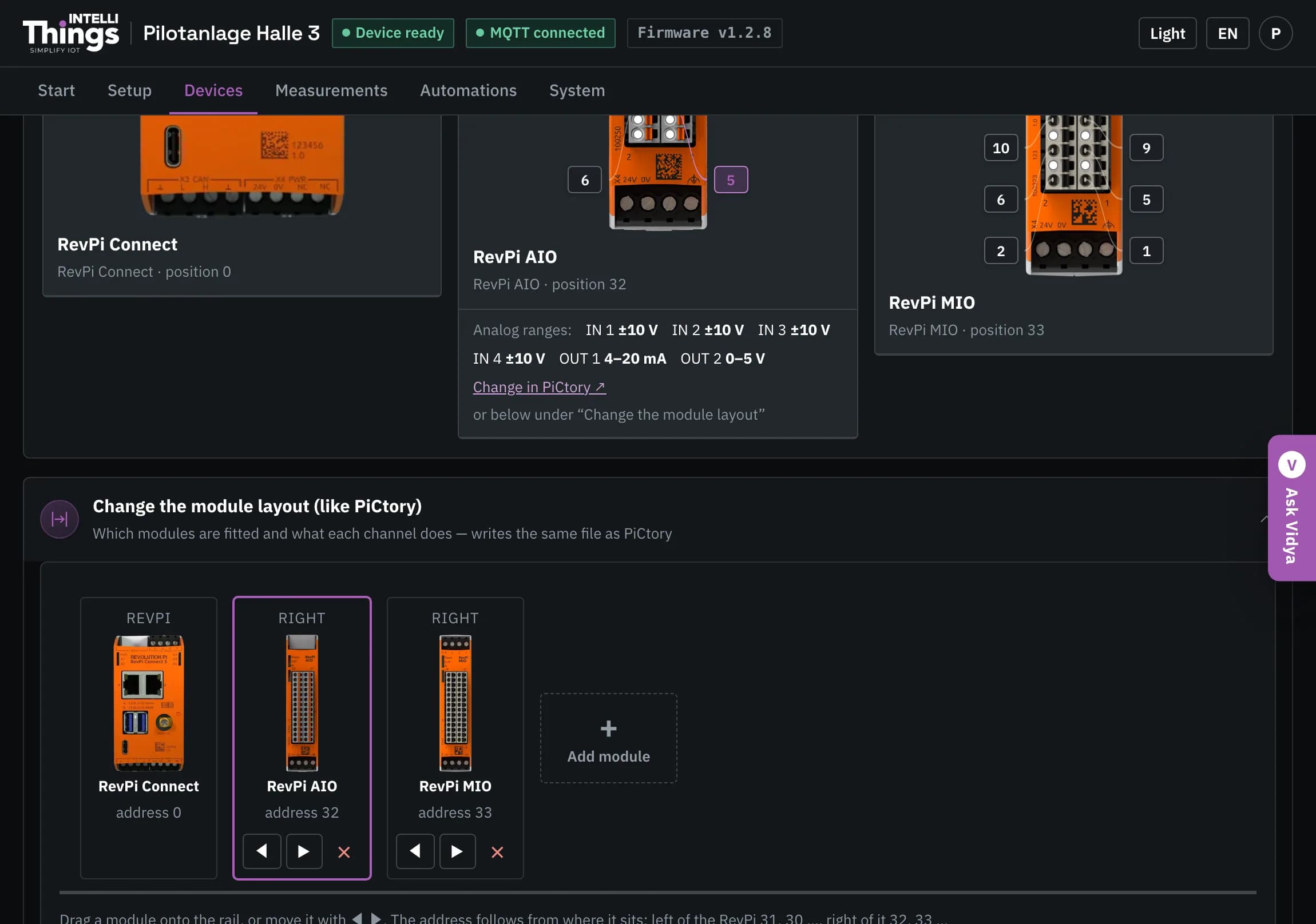
- View the layout: the on-screen rail shows the RevPi and its expansion modules. Each module has a photo and an address.
- Add a module: click + Add module at the end of the rail.
- Move or remove a module: drag it or use ◀ ▶ to change its position. Click ✕ to remove it. Module addresses are assigned automatically based on position.
- Configure a channel: select a module, then a port in its photo. Choose the required range or function, such as ±10 V, 4–20 mA, PT100, PWM or counter. Only settings supported by the module are available.
- Restore a layout: every change is backed up. Use Earlier layouts to restore a previous layout.
If the + tile is missing, no module templates are installed on the RevPi. You can still move and configure existing modules.
Applying the module layout briefly switches off all outputs
Module layout changes take effect only when you click Restart I/O and apply. This reloads the I/O driver and switches every output off for about one second. Never apply the layout while the connected equipment is running. Before applying changes on an unfamiliar RevPi, compare the module list with the hardware in the cabinet.
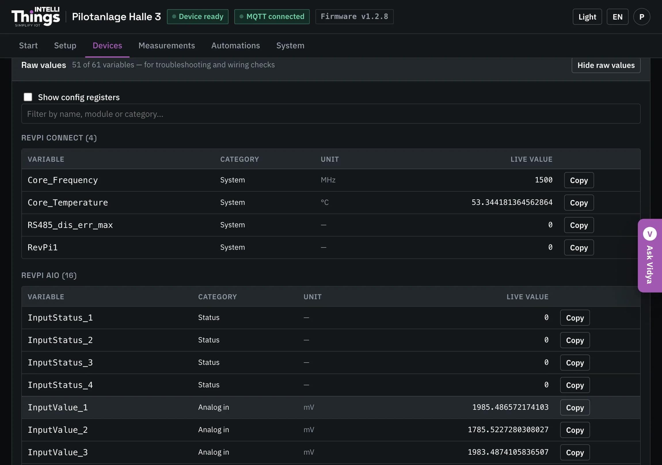
View raw signal values
At the bottom of the page, Show raw values lists all signals available from the modules and their live readings. Use this view to check whether a port is receiving a signal. You can filter the list and use the Copy button on each row.
These are raw hardware readings, before scaling and rounding, rather than the values sent to the platform. The dashboard refreshes them every two seconds. For an output, the list shows the value currently applied, whether it was set by an automation rule, a platform command or the Test box.